The practical answer.
Approve a connector substitution against the pack-to-equipment interface drawing. Match both mating part numbers and the pin map, then validate the assembled harness at the equipment's electrical and mechanical boundaries. A connector that fits and powers the device at idle can still fail at startup, when the harness is strained or when the wrong revision is fitted during service.
- Identify both sides of the connector and specify the drawing view used to number pins.
- Separate contact and crimp loss from the voltage drop of the complete installed path.
- Release the alternate with an approved equipment revision, tooling record and evidence.
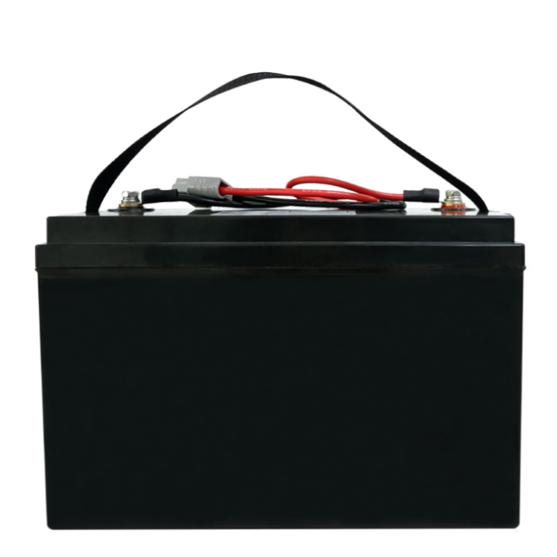
Define the change on both sides of the equipment boundary
A substitution may begin with a supplier notice, a revised housing or a purchasing request to qualify a second source. Record whether the proposal changes just a terminal or a complete pair. If only the battery-side part changes, it must mate with equipment already in the field as well as current production. If both halves change, the compatibility matrix must tell production and service which combinations are authorized.
Jetray's industrial pack reference material treats the BMS, leads and connector as separate fields. Use that separation when requesting a quotation. Give the battery supplier the equipment drawing revision and keep the connection hardware on a controlled drawing. A pack voltage and capacity can stay the same while its harness changes enough to require a separate equipment review.
| Changed item | Evidence the buyer should request |
|---|---|
| Housing or mating half | Exact part numbers, keys, mating drawing and equipment revisions affected |
| Terminal or plating | Matched contact pair and wire range, application specification and environmental evidence |
| Lead length or routing | Installed drawing with bend space, restraint and service access |
| Crimp tool or assembly process | Approved application instructions and results on production-representative leads |
| Power and signal assignments | End-to-end map with function, polarity and specified drawing view |
Make the pin map unambiguous before testing
Place the mating-face view beside the wire-entry view. Mirrored views can make a correct layout look reversed, so label the orientation by reference to the latch or key. Map battery positive, return, sense, wake, enable and communication pins only where those functions actually exist. Document unused cavities and any seals. Wire color can help assembly staff identify a lead, but the drawing and end-to-end checks control the pin assignment.
Confirm whether the equipment detects a disconnected signal or uses any defined contact sequence. If the old and new connectors can physically cross-mate but wire differently, address the risk through the equipment release plan before introducing the alternate into inventory. A new label alone is a weak control when connectors look alike in a crowded service bay.
Put numbers around the voltage available at the equipment
Keep a voltage allowance for the proposed interface. In an illustrative design, the pack may deliver 20.4 V at its output under a specified 12 A operating condition. If the equipment requires 20.0 V at its own input at that instant, the whole path has 0.4 V of headroom. Suppose 0.22 V is reserved for leads, fusing and their connection points, and 0.06 V for measurement and design margin. That leaves 0.12 V for the connector interface as defined on the drawing.
At 12 A, a 0.12 V allocation represents 10 milliohms for the combined positive and return paths across that measurement boundary. The associated loss is 1.44 W across the pair at that current. Those values are illustrative requirements, not limits for a particular Jetray product or connector. If the proposed part reaches the voltage allocation, its temperature rise can still fail the equipment design because of a sealed housing, nearby heat or several simultaneously loaded contacts.
A qualified lab can use a suitable four-wire resistance method on an unpowered representative assembly and a separate loaded voltage-drop and temperature test in the actual harness arrangement. Keysight describes the use of separate current and sense leads for low resistance measurements. Record exactly where the sense points land, because moving them past a crimp changes what the result includes. Compare the alternate and baseline at the same points and under the same conditions.
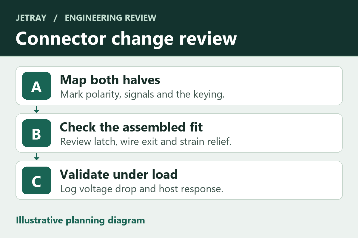
Check the installed pair through assembly and service
A trial at the bench should use both intended mating parts, the production conductor and the specified crimp tools. Compare latch engagement, terminal seating and cable strain relief when the harness is routed through the equipment. Look for a position where the cable can pull on a terminal, the latch cannot be reached or a nearby bracket presses against the connector as the cover closes.
Ask for the application limits for the chosen connector family rather than assuming that the highest printed current applies to every wire size, contact count or ambient condition. Molex distinguishes retention, contact materials and the intended operating environment in its connector engineering guidance. Use project-specific exposure and service cycles to select the evidence you need from the component maker and the assembled-harness supplier.
- Freeze the baseline drawing and record the affected host and pack revisions.
- Review the new mating pair, pin map, wire range, terminal material and retention method before sample approval.
- Ask the test team to document the installed fit and measure voltage at both sides of the path under the defined load.
- Record the authorized combination in the bill of materials and service documentation before ordering production quantities.
Common questions during alternate-part approval
Can the supplier substitute a terminal inside the same housing?
Treat the terminal as a controlled part. The mating contact, wire gauge, plating and crimp process still need to match the application specification. Confirm that the housing retention feature engages the proposed terminal and that the installed assembly meets the required electrical boundary.
Does a passing continuity check establish power-path suitability?
Continuity establishes connection through the intended path under the conditions of that check. Loaded voltage drop, localized heating and retention require their own evidence. A continuity result belongs in the release packet alongside these separate checks.
Sources & further reading
- Jetray lithium-ion battery pack catalog and OEM configuration overview ↗
- Molex connector contact retention engineering guidance ↗
- Keysight four-wire resistance measurement method ↗
The voltage budget illustrates a method. A connector, harness or pack can only be approved against its actual drawing, equipment and test conditions.
Prepared for the lithium-ion battery packs collection. General engineering guidance does not replace a model-specific datasheet or application validation. Source review: 5 November 2026.